Fusor Neutron Generator

The fusor is a remarkably simple apparatus for producing nuclear interactions between deuterium ions by accelerating them with high voltage electrostatic fields. This post describes the basic theory of operation, construction, and operation of a small low-power fusor that is nevertheless capable of generating a measurable number of neutrons. A notional parts list and references are provided at the end.

Table of Contents

  1. Operating Principle
  2. Safety Information
  3. Vacuum Chamber
  4. Vacuum Pump
  5. Deuterium Supply
  6. Vacuum Gauge
  7. High Voltage Feedthrough and Cathode
  8. High Voltage Power Supply
  9. Neutron Detector
  10. Operation
  11. Experimental Results
  12. Parts List
  13. References

Operating Principle

From an electrical standpoint, the fusor is a two-terminal glow discharge device with qualitative behavior similar to that of a neon tube. The key difference is that the fusor operates in a regime with lower pressure and smaller separation between the two terminals. Consequently, charged particles (electrons and, more importantly, deuterium ions) are able to achieve very high velocities corresponding to the full acceleration voltage of around 22.5 keV. When two deuterium ions collide at such high velocities, there is a small but measurable probability that the two will interact in the following way, producing a neutron:

{^{2}_{1}H} + {^{2}_{1}H} \rightarrow {^{3}_{2}He} + {^{1}_{0}n} + 3.27MeV

In order to maximize the probability that two positively-charged deuterium ions will collide after being accelerated to maximum velocity, the fusor architecture consists of a small grid-like cathode (negatively-charged electrode) surrounded by a metal vacuum chamber that forms the anode (typically grounded, but positive relative to the cathode). The original fusor invented long ago by Philo Farnsworth had a spherical layout, but the one described in this post has a more linear / tubular form factor. Deuterium ions that are formed on the left and right sides of the chamber are accelerated into the centrally located cathode loops, where they have a good chance of colliding with ions travelling in the opposite direction.

Safety Information

  • WARNING: The device described in this post is capable of producing X-rays, ultraviolet light, and a small number of neutrons. The experimenter is responsible for ensuring that no one is exposed to harmful levels of radiation.
  • WARNING: High voltage can cause serious injury or death.
  • WARNING: Deuterium gas is highly flammable.
  • WARNING: All information in this post is provided as-is, free of charge, with no warranty, and for informational purposes only. The experimenter is solely responsible for ensuring safe construction and operation of the device, as well as compliance with any regulatory, legal, or safety-related requirements.

More detailed safety information can be found in the references. Of all the risks associated with operating a fusor, X-ray safety is arguably the most challenging to address. One approach to help mitigate this risk is to construct the vacuum chamber entirely from stainless steel. X-rays produced by 22.5kV discharges have very limited ability to pass through stainless steel or lead, but are able to travel much more easily through other materials such as glass. A second mitigation approach is to stay as far away from the device as possible during operation, as radiation intensity varies inversely with distance squared. Again, this entire post is provided for informational purposes only. The experimenter is responsible for taking all necessary safety precautions, whether or not they are identified in this post.

Vacuum Chamber

The fusor is built around a small vacuum chamber that serves both to maintain a low-pressure deuterium atmosphere and as the grounded anode. The vacuum chamber is a standard KF-50 to KF-25 reducing cross. A cooling fan is also visible in the picture below. Some discoloration of the stainless steel vacuum chamber is evident. This was caused by a previous experiment where the temperature reached excessive heights due to absence of the fan and higher-power operation.

The KF-50 ports may both be covered with blanks, or one of them may be covered with a glass view-port. In the latter case, special precautions must be taken to ensure that no one is exposed to X-rays emitted from the glass port. In any case, the main purpose of having the two capped-off KF-50 ports (instead of using a simple KF-25 straight pipe as the vacuum chamber) is to provide the proper chamber geometry that enables a stable glow discharge to form.

The top of the reducing cross accommodates the high voltage feedthrough and electrode assembly. The bottom is connected to a standard KF-25 four-way cross that links up the vacuum chamber with the diffusion pump, the deuterium source, and the vacuum pressure gauge.

Vacuum Pump

The first step in establishing a low-pressure deuterium atmosphere inside the vacuum chamber is to create a vacuum of below 1 micron. This can be achieved using an oil diffusion pump, backed with a two-stage rotary vane pump.

Oil diffusion pumps are often available on the second-hand market. The one pictured below was probably removed from an old scanning electron microscope. It was acquired for around $150 dollars, but substantial effort was required to refurbish the internal parts which were covered in burned oil. Also, a water cooling system was built using standard PC liquid cooling components. Diffusion pump oil had to be purchased separately, and a 200 volt transformer was also needed. The water-cooled baffle above the pump was purchased separately for around $300. Connection of the non-standard output to the KF-25 cross was a bit of a challenge. A custom adapter (aluminum part above the baffle) was designed using software from emachineshop.com and purchased for a few hundred dollars more, and a gate valve (at very top of the picture) was connected to it. Then, an ISO-63 to KF-25 adapter was used to connect the flat surface of the top of the gate valve body to the KF-25 four-way cross from the previous section. The ISO-63 flange was mated to the gate valve body using a 1/16″ nitrile rubber gasket ring that was cut from a flat sheet.

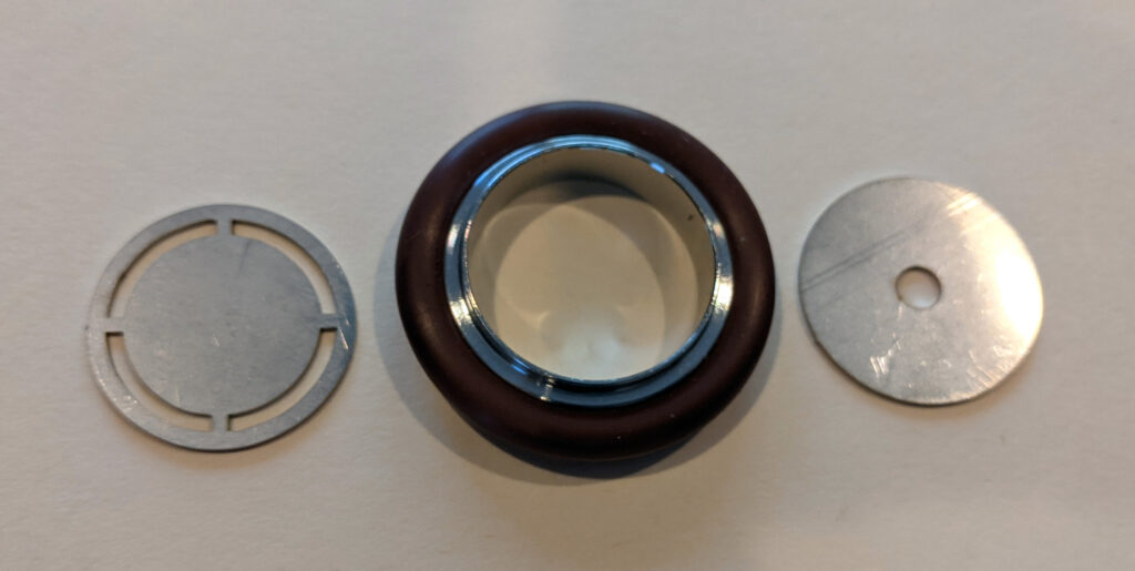
Unfortunately, the gate valve turned out to be less than useful. The intended purpose of the gate valve was to prevent the powerful diffusion pump from sucking out all of the deuterium gas too quickly. Unfortunately, even when fully closed, the gate valve allowed too much deuterium outflow because it had too loose a gap between the butterfly and the valve body. Instead, a fixed flow restrictor was inserted into the KF-25 connection between the ISO-63 adapter and the KF-25 cross. This was just a simple disk of 1″ outside diameter with an approximately 1/8″ hole in the center. The disk was placed inside the KF-25 connection, with the metal centering ring and 1″ tube holding it in place. This simple part was designed using Adobe Illustrator and fabricated by sendcutsend.com. To prevent high-energy electrons from escaping from the chamber, a second round part with four outer vent holes was also created, and the centering ring was sandwiched between these two custom parts (all shown below).
Vapor diffusion pumps require a backing pump. Vacuum equipment suppliers provide high-quality rotary vane pumps for this purpose, but I used a more economical refrigeration service pump, the Robinair 15500 VacuMaster. The pump inlet had to be replaced with a 1/2″ barbed tubing connector, which was then connected to the diffusion pump’s non-standard outlet using a custom-made bracket, flange, and flat nitrile rubber gasket. A second pump is also pictured, but a single pump should be sufficient. The yellow hose from the second pump is connected to a second vacuum gauge that is also not required.

IMPORTANT NOTE #1: The connection between the diffusion pump and the backing pump must be as short and thick as possible. If this connection presents a substantial bottleneck, the pressure at the diffusion pump outlet will build up to such a high level that the pump will either fail to operate or may begin to oscillate. If the vacuum chamber pressure appears to be fluctuating periodically, the most likely causes are (1) insufficient backing pump capacity, (2) inadequate tube thickness, (3) excessive tube length, or (4) excessive deuterium flow.

IMPORTANT NOTE #2: There is one undesirable side-effect of replacing the mechanical pump inlet manifold with a tubing connector. The OEM pump inlet also contains an integrated check valve that prevents the mechanical pump’s oil from getting sucked out if the pump is turned off while it is still connected to a vacuum. If this check valve is removed when the inlet fitting is changed, it is imperative that air be released into the vacuum chamber before shutting down the mechanical pump.

Deuterium Supply

Due to fire safety considerations, the deuterium tank is never connected directly to the apparatus. Instead, a small amount of deuterium is first transferred to a latex party balloon. This balloon is then attached to a tubing connector that feeds a precision needle valve, which is connected to one of the ports on the KF-25 cross. The balloon port is just a piece of left-over 1/2″ hose on a barbed nylon fitting (see parts list for the nylon fitting).

Vacuum Gauge

The most economical gauge for measuring pressures in the 1 micron to 50 micron range of interest is a thermocouple gauge. I used an inexpensive VMV-1 gauge purchased from eBay. It was connected to the KF-25 cross using a couple more adapter parts (see parts list).

High Voltage Feedthrough and Cathode

The most interesting part of the design is the high voltage feedthrough and cathode assembly. It must not only support a high voltage potential, but must also provide a tight vacuum seal. Furthermore, the inner part of the assembly will become white-hot when it is bombarded with high-energy ions, precluding the use of any plastics or other low-temperature materials. Ideally, the assembly should be constructed from refractory metals like tungsten and refractory ceramic insulators such as alumina.

Luckily, it is possible to construct such an assembly without the use of any special metal-ceramic sealing techniques. Instead, a KF-25 to 1/2″ vacuum connector creates an O-ring seal between the alumina tube and the vacuum chamber body. Then, a 1/2″ to 1/8″ adapter with PTFE ferrules is used to seal a 1/8″ pure tungsten rod to the inside of the alumina tube. The adapter does need to be through-bored so that the tungsten rod can pass all the way through, but this can easily be accomplished using a drill and vise or a drill press. Do be careful not to scratch the fitting surfaces that seal against the PTFE ferrules. The most challenging part of the fabrication process is the drilling of a small hole at the end of the tungsten rod, from which to hang the inner grid. I used 1.45mm short length carbide drill bits for this purpose. A small drill press (or better yet, a rotary tool stand) as well as eye protection are definitely required, and drilling several practice holes in a scrap tungsten rod is probably a good idea as well.

The alumina tube is approximately 9″ long, 1/2″ outside diameter, and 1/4″ inside diameter. It is cut from the 12″ tube in the parts list below using a BOSCH DB1043S blade attached to a miter saw, or using a similar but smaller diamond blade attached to an angle grinder. WARNING: Safety goggles and/or face shield are required during cutting.

The actual grid is made from a 1/25″ pure tungsten electrode. Unfortunately, tungsten is too brittle to bend into the required shape at room temperature. However, once it is heated using a blow torch, it can be bent around a metal object such as a bolt to form a 1.15 cm diameter multi-turn coil as shown. Then, the grid is threaded through the hole in the previously described 1/8″ tungsten rod.

Once the entire assembly has been constructed, it is installed in the top-most KF-25 port of the reducing cross. The hole in the coil should be aligned with the long axis of the reducing cross.

High Voltage Power Supply

The high voltage power supply made by the author of this post is available for purchase on eBay:

25kV Negative High Voltage Adjustable Power Supply – AN-25K-50W

The negative high voltage output cable of the power supply is connected to the cathode using the screw terminal butt splice shown in a previous section (see parts list), and the ground lug on the chassis is connected to the vacuum chamber using bare copper wire.

Neutron Detector

I used a Helium 3 neutron detector made by Maximus Energy. The particular model that I purchased appears to have been discontinued, but the NEUTRON-LITE-SI19N is probably a good substitute. Helium 3 detectors are very sensitive to slow neutrons, but the fusor produces fast neutrons. Therefore, the detector is placed inside a 6″ diameter x 12″ long HDPE cylinder with a long bore hole.

Operation

Once the device has been constructed, the first step is to test the vacuum system. The deuterium valve should be closed just until some resistance is encountered. Over-tightening will easily damage this precision valve. Then, the mechanical pump can be turned on. If there are no leaks, a properly functioning two-stage rotary vane pump should be able to bring the pressure down to 50 microns or lower, as measured by the vacuum gauge. Then, the diffusion pump heater, fan, and water pump (if applicable) should be turned on. After approximately 20 minutes, the chamber pressure should drop to below 1 micron. At this point, a latex party balloon containing a small amount of deuterium can be connected to the valve. Care should be taken to avoid contaminating the deuterium with too much air from the atmosphere.

To adjust the pressure, the valve is opened slowly until the gauge shows around 13.9 microns. A very stable reading is required because otherwise, it will not be possible to maintain a glow discharge at the necessary voltage and current levels. If the pressure appears to be oscillating up and down periodically, the pumping system may be unable to support the amount of deuterium flowing through the system. One possible solution is to use a flow restrictor with a smaller hole. This will allow the chamber pressure to reach a higher level without overwhelming the pumps with too much exhaust. On the other hand, if the flow restrictor hole is too small, the pressure may fluctuate too wildly when power is turned on.

When power is turned on, a glow discharge should form between the cathode loop and the grounded body of the vacuum chamber. WARNING: Proper care must be taken to ensure that no one is exposed to X-rays when the high voltage power supply is on. As the voltage is increased above a certain threshold, a small amount of current (around 1 or 2 mA) should begin flowing. If almost no current flows, the pressure is probably too low and the deuterium valve should be opened just a little at a time. On the other hand, if the current starts to increase too rapidly before the voltage reaches 22.5 kV, the pressure may need to be reduced. WARNING: Don’t get too close to the high voltage connector while the power supply is on! Instead, turn it off, make the pressure adjustment, and then turn it back on. After some experimentation, the best operating point for producing neutrons within the constraints of this small power supply was found to be approximately 13.9 microns, 22.5 kV, 2.0 mA.

After the power supply is turned off, the diffusion pump should be allowed to cool down with the fan and water pump (if applicable) still on. Only then should the mechanical rotary vane pump be turned off. CAUTION: To avoid creating a huge mess, make sure to release the vacuum (by opening a valve or removing a cap) right before turning off the rotary vane pump. Otherwise, oil will be sucked out from the rotary vane pump and into the diffusion pump. If this happens, both pumps will require an oil change! If the rotary vane pump inlet has a back-suck prevention valve, this may not apply.

Experimental Results

Helium 3 spectrometers are very sensitive when it comes to detecting small numbers of neutrons, but they also produce spurious background counts. Furthermore, X-rays and electromagnetic interference can also produce counts, making it difficult to confirm that counts actually correspond to neutrons.

Luckily, there is an idiot-proof method to confirm that counts are actually being caused by neutron interactions. If two identical experiments are performed – one with the HDPE moderator and one without the HDPE moderator, and the experiment with the moderator has a significantly higher count than the one without, this confirms that neutrons were actually being detected. Even at a very modest power level of approximately 22.5 kV at 2 mA (45W), a strong level of statistical confidence that neutrons are being produced can be obtained in 10 minutes:

ExperimentTotal Counts (10 min)
Background17
HV On, No Moderator26
HV On, With Moderator217

This quick video (recorded after completion of the more systematic 10 minute experiments listed in the table) shows how the count rate drops when the moderator is removed:

Parts List

The following notional parts list includes most of the components and raw materials that were used to build this system, except for the vacuum pumps and associated parts / accessories. Some of the items were actually obtained from used/surplus suppliers on a one-off basis to reduce cost, but a similar brand new item from an easy-to-work-with supplier is listed here instead even though the cost may be several times higher than that which a determined scrounger would pay. Deuterium gas is also not listed here. Most specialty gas suppliers have the ability to provide it, but are only willing to sell to companies, not individuals.

Some NPT connectors are used in this design. NPT connections are not ideal for vacuum applications. However, they can provide an adequate seal with some caveats: (1) Apply around 1 1/2 turn of PTFE tape to the joint by turning the male pipe in the same direction that will be used to tighten it (so that the tape doesn’t come off during tightening). (2) Avoid purchasing the NPT fittings from non-US suppliers. Some sellers market BSPT fittings as NPT because they look almost identical, but NPT and BSPT fittings will not form a proper seal. (3) Brass-to-brass or brass-to-stainless-steel connections seem to form a better vacuum seal than stainless-to-stainless-steel, possibly because brass is more deformable. This is just an anecdotal observation of mine.

DescriptionPart #SupplierQtyTotal
Reducer Cross KF-50 to KF-25P102658Ideal Vacuum1$230.00
KF-25 to 1/2 in CompressionP103773Ideal Vacuum1$89.47
KF-50 Blank FlangeP102320Ideal Vacuum2$38.18
Hinge Clamp KF-50 AluminumP101201Ideal Vacuum2$25.18
Centering Ring KF-50 Stainless SteelP101245Ideal Vacuum2$31.40
4-Way Cross KF-25P101206Ideal Vacuum1$140.07
Hinge Clamp KF-25 AluminumP101199Ideal Vacuum5$44.55
Centering Ring KF-25 Stainless SteelP101243Ideal Vacuum5$39.95
KF-25 to 1/4 NPT-FemaleP101310Ideal Vacuum2$50.48
Tungsten Rod, 1/8″ x 12″5137N7McMaster1$66.17
Tungsten Electrode, 0.04″ x 7″8000A522McMaster1$3.97
Alumina Tube, 1/2″ x 1/4″ x 12″8746K19McMaster1$35.40
Yor-Lok Straight Reducer 1/2″ to 1/8″5182K246McMaster1$42.73
Yor-Lok PTFE Sleeves, 1/8″5182K974McMaster1$8.03
Yor-Lok PTFE Sleeves, 1/2″5182K977McMaster1$6.91
Screw-down Butt Splice6922K51McMaster1$4.09
High-Precision Valve7832K21McMaster1$112.67
1/8″ NPT-Male to 1/4″ NPT-Male5485K31McMaster1$2.44
1/8″ NPT-Male to 1/4″ NPT-Female50785K26McMaster1$1.70
1/4″ NPT-Male to 1/2″ Barbed Nylon2974K137McMaster1$8.68
Vacuum GaugeVMV-1eBay1$121.60
1/4″ Flare to 1/4″ NPT-Male50635K374McMaster1$2.01
Helium 3 Neutron DetectorNEUTRON-LITE-SI19NMaximus Energy1$995.00
HDPE 6″ x 12″ Rod8624K58McMaster1$136.97
25KV Negative HV Power SupplyAN-25K-50WeBay1$798.00
TOTAL (not including pumps, D2)$3035.65

References

fusor.net – This forum is the largest single source of information on everything fusor-related. Many experimenters have posted useful information about their work here, and the author of this article would like to thank all the participants of this vibrant community for their valuable contributions. Special thanks to Richard Hull, Andrew Seltzman, Mark Rowley, Liam David, and Steven Haid for their particularly helpful posts.

Electrical Discharges – A good introduction to general theory of sparks, glow discharges, and arcs. This sort of background knowledge is essential for understanding how the fusor works at the level of electrons and ions, and can be very helpful when it comes to diagnosing failures.

Diane’s Fusor Page – This page has lots of info on fusor theory, and also describes some interesting fusor-related experiments.

Building Scientific Apparatus – An excellent textbook on experimental technique in general. The chapter on vacuum technology is especially thorough and relevant to fusor construction. The book also contains info on electronics and particle detection.

Effect of Dataset Size on Image Classification Accuracy

The accuracy of a machine learning system depends on the complexity of the model that it uses to make predictions, as well as the number of data instances available for training this model. The experiments described in this post are designed to evaluate the performance of three ResNet image classification models, each with a different number of layers. These models were trained using 50,000 images from the CIFAR-10 dataset, but were also trained separately using smaller subsets of the CIFAR-10 dataset.

The CIFAR-10 Dataset

The CIFAR-10 dataset consists of 60,000 low-resolution images. These images are so small (32 pixels on each side) that even a highly complex model can be trained on a single GPU in a matter of hours. Each image in the CIFAR-10 dataset is labeled as a member of one of 10 mutually exclusive classes. The images are split up into a training set (50,000 images) and a test set (10,000 images).

ResNet

Convolutional Neural Nets (CNNs) are very good at solving image classification problems, and the ResNet architecture is a popular type of CNN. I decided to run experiments on three different ResNets, with as few as 8 and as many as 56 layers. I wrote a program that builds, trains, and evaluates a ResNet on the CIFAR-10 dataset using TensorFlow:

github.com/seansoleyman/cifar10-resnet

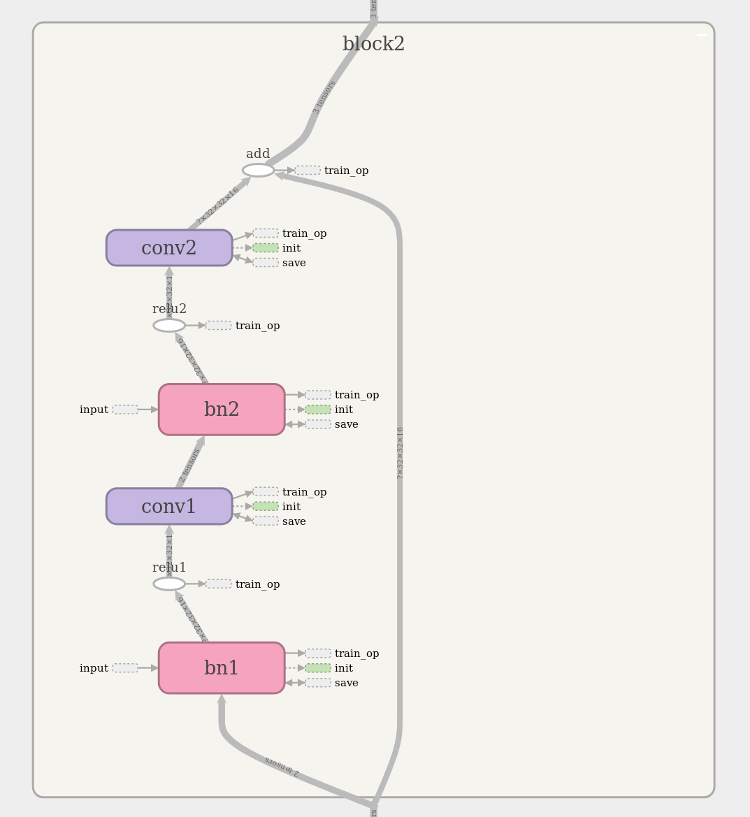
This program permits training on a subset of the full CIFAR-10 training set. The ResNet architecture can be visualized interactively using TensorBoard. The TensorBoard image below shows a ResNet block with two layers. As an example, ResNet-56 consists of 27 similar blocks stacked one atop the other, plus a few more layers at the top and bottom of the stack. The references at the end of this post provide detailed information about CNNs and ResNets.

Experimental Observations

Here are the results that were obtained after training three different ResNets on subsets of the CIFAR-10 training set. Each data point represents the test set error rate that was achieved after training the model on a certain number of images. For example, the models on the very left hand side of the graph were trained on just 500 images, and the ones on the right hand side were trained on all 50,000.

Conclusions

Although it is well known that increasing the amount of training data increases the performance of a model, it is interesting that the relationship plotted above follows such a well-defined exponential decay pattern. The error rate appears to approach an asymptotic limit as the amount of training data is increased.

It looks like it would be possible to fit an exponential decay function to the points plotted above. This exponential function could then be used to extrapolate and predict the performance that a model would achieve if more training data were available.

References / Links

  1. Aurelien Geron, Hands-On Machine Learning with Scikit-Learn and TensorFlow: Concepts, Tools, and Techniques to Build Intelligent Systems
  2. Ian Goodfellow and Yoshua Bengio and Aaron Courville, Deep Learning (available online)
  3. Kaiming He et. al., Deep Residual Learning for Image Recognition
  4. Kaiming He et. al., Identity Mappings in Deep Residual Networks
  5. Alex Krizhevsky, Learning Multiple Layers of Features from Tiny Images

Vacuum Chamber with Oil Vapor Diffusion Pump

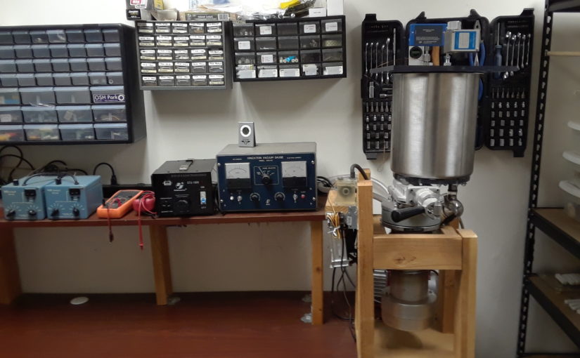
This three-stage vacuum pumping system creates a very strong vacuum, in which charged particles can travel long distances without colliding. It has a large stainless steel vacuum chamber with a transparent cover. When paired with a high voltage power supply, it can be used for experiments involving electron beams, ion beams, etc.

Warnings

  • There is always a chance that a home-made vacuum chamber may implode.
  • If left un-attended, the diffusion pump heater will create a fire hazard.
  • High voltage vacuum experiments have the potential to generate harmful X-Rays.

Components

  • Two-Stage Rotary Vane Pump
  • Foreline Pump Hose
  • Vapor Diffusion Pump
  • Liquid Cooling System
  • Vapor Baffle
  • Gate Valve
  • Vacuum Chamber
  • Variable Leak Valve
  • Convection Gauge
  • Bayard-Alpert Ionization Gauge

Two-Stage Rotary Vane Pump

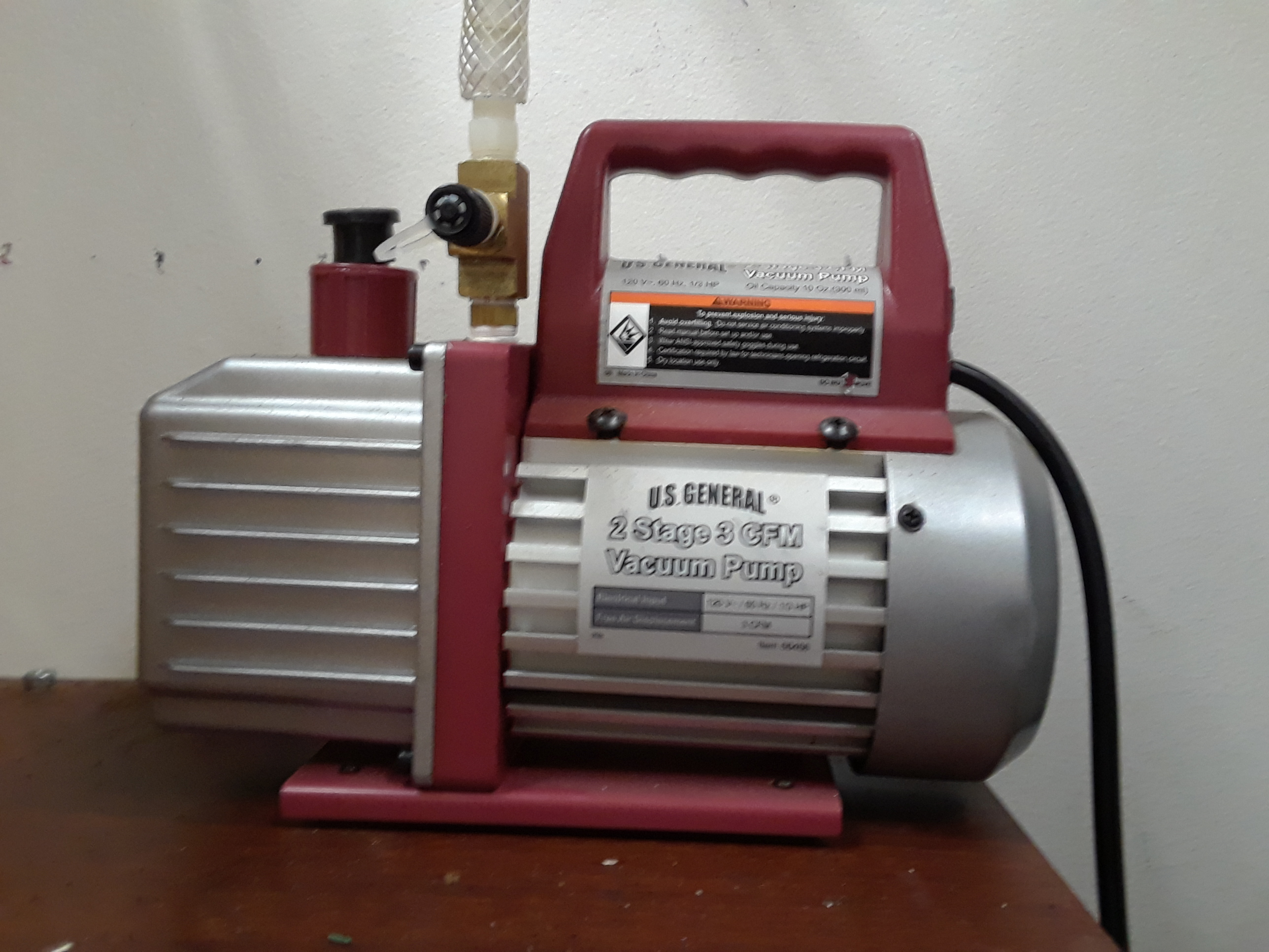
The two-stage rotary vane pump is a mechanical pump that brings the system pressure down to about 30 microns Hg. It was purchased brand-new from Harbor Freight Tools.

Foreline Pump Hose

Originally, I tried to use an r134a refrigerant charging hose to connect the rotary vane pump to the oil diffusion pump. Unfortunately, the inside diameter of this hose was only about 3/16″ and this created an unacceptably large pressure differential between the diffusion pump exhaust and the rotary vane pump inlet. To solve this problem, I un-screwed the flared fitting that came with the rotary vane pump and connected the pump to a 1/2″ fiber-reinforced flexible plastic tube. A cork-shaped silicone plug was used to join the other end of the tube to the diffusion pump. Nylon barbed tube fittings were used on both ends of the tube.

Oil Vapor Diffusion Pump

I purchased a used 4″ vapor diffusion pump from eBay. It appears to have been salvaged from a JEOL scanning electron microscope, and was in very dirty condition when I received it. This pump was the victim of a careless operator. It is very important to make sure that the rotary vane pump is turned on before the diffusion pump heater, because otherwise the oil will burn and create a huge mess. I dis-assembled the pump and was able to clean out most of the burned oil by scrubbing it with soap water and a wire brush. I purchased a bottle of replacement oil directly from Kurt J Lesker Company.

Liquid Cooling System

The radiator was salvaged from an old Power Mac G5 computer, and the water pump was purchased from eBay. Rubber tubing was used to make all the connections. Two computer fans are used to force air through the radiator. Unfortunately, this system is not large enough to handle the 500W heat output. The radiator becomes too hot to touch after about 20 minutes. A radiator from a small car would probably be more appropriate. Proper cooling will improve the overall performance of the pump by causing the oil vapor to condense as soon as it hits the walls of the pump.

Vapor Baffle

The system functions just fine without a vapor baffle, but I was lucky enough to find a matching baffle for my diffusion pump on eBay. It helps to prevent oil vapor from escaping into the vacuum chamber.

Gate Valve

When the diffusion pump is starting up, it may spew hot oil vapor into the vacuum chamber unless the gate valve is closed. I purchased a used 2″ gate valve from eBay for about $30. I had to replace all of the O-Rings, and I also noticed that vacuum grease had been used on the valve. I purchased a tube of Dow Corning vacuum grease from eBay, and started using it on all of the rubber O-rings and gaskets. A 3/8″ aluminum plate is used to connect the diffusion pump inlet to the gate valve. Nitrile rubber O-rings are used to seal both connections.

Vacuum Chamber

The vacuum chamber is built around a large Bain Marie pot that I purchased from Food Service Warehouse. It is constructed from heavy-gauge sheet metal, and does not have any handles that could potentially leak air into the chamber. Although the cylindrical portion of the pot seems to be structurally sound, I suspect that the flat base could crumple under full vacuum. Therefore, I created a 1/2″ polycarbonate reinforcement plate to take all pressure off the stainless steel base. 14 bolts are evenly spaced around the perimeter of the base, and a 1/16″ nitrile rubber gasket seals the stainless steel chamber to the polycarbonate plate. Some of the bolt holes are sealed with JB-Weld, a slow-setting epoxy resin. After mixing the epoxy, I de-gassed it for about a minute in an ordinary vacuum chamber. The remaining bolt holes are sealed with special screws (from McMaster) that come with built-in O-ring seals. During operation, the vacuum chamber is covered with a 1/2″ polycarbonate plate. This allows the inside of the vacuum chamber to be viewed, and also makes it easy to change between different experiments (by using a different chamber cover for each experiment). The cover seals against the rounded stainless steel edge with a 1/16″ nitrile rubber gasket sheet.

Variable Leak Valve

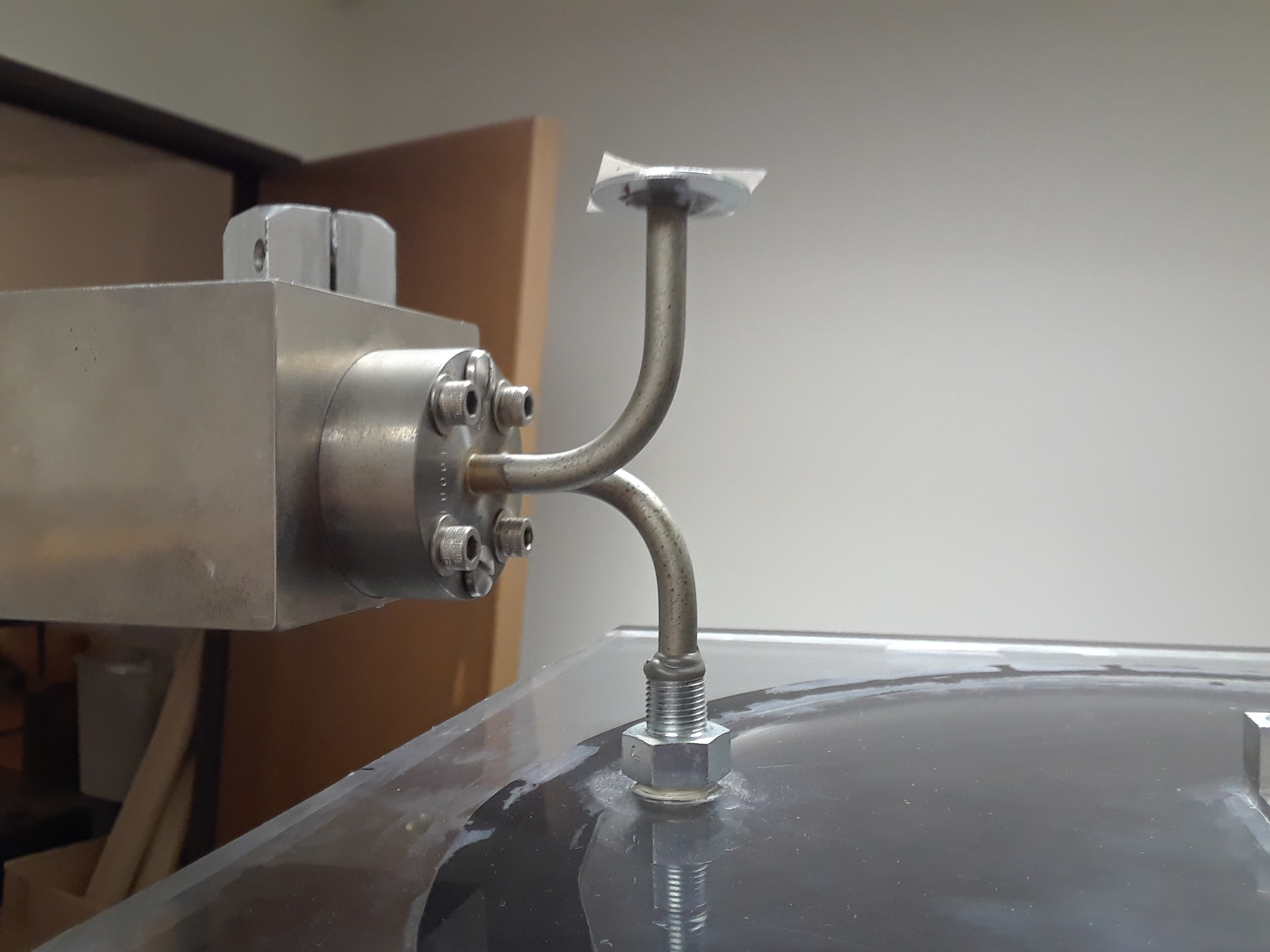
I purchased a variable leak valve on eBay. This is an unusual item, and I had to wait a while for one of them to come on the market. A variable leak valve can be used to introduce very small amounts of gas into the vacuum chamber. This is necessary for certain experiments, such as the fusor. JB Weld was used to attach the leak valve to a 1/4″ NPT fitting, which was then screwed into a hole that was tapped in the polycarbonate cover. PTFE paste was used to seal the NPT fitting.

Convection Gauge

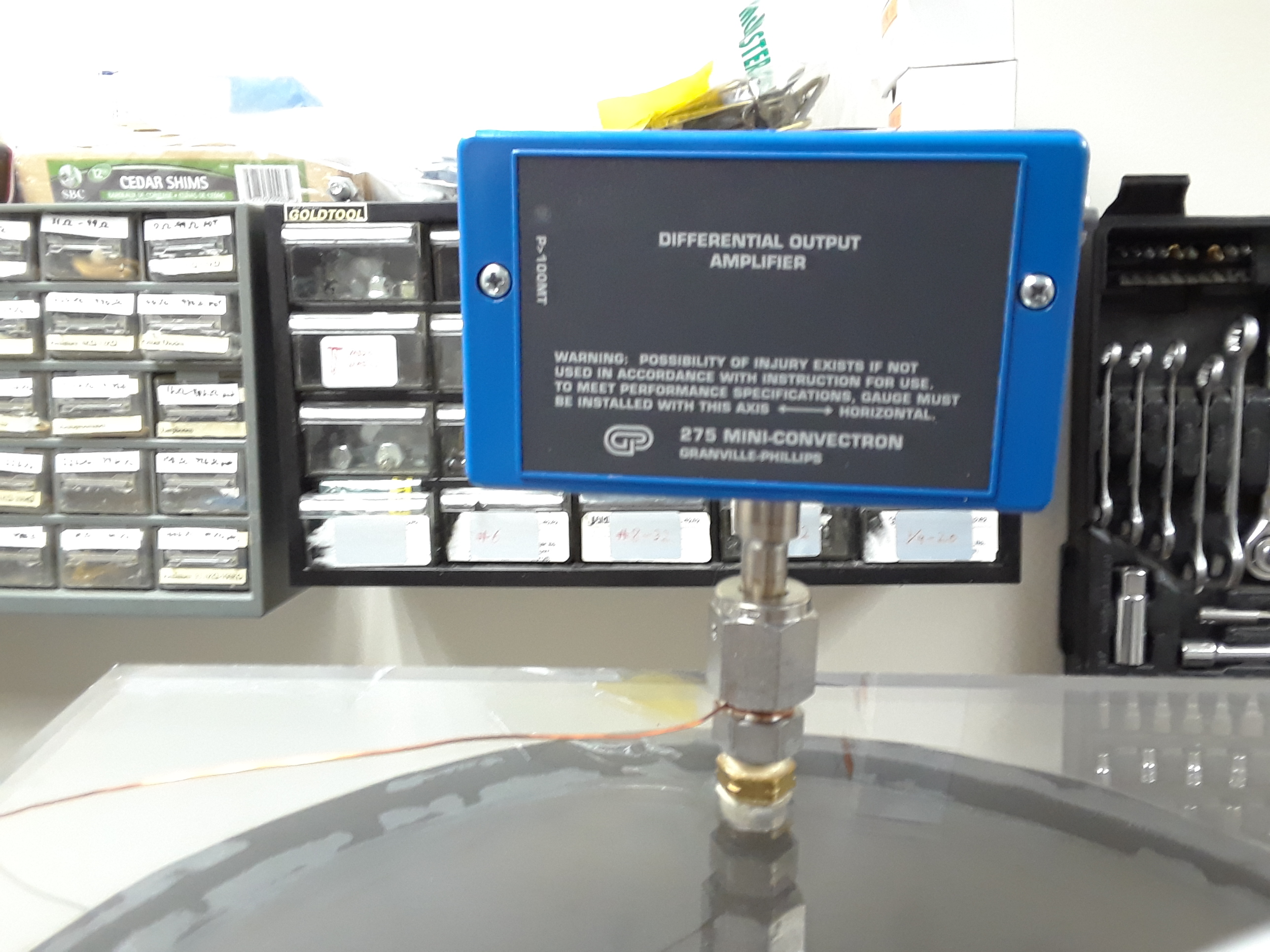
A convection gauge is fitted to the top of the vacuum chamber cover. The convection gauge has a special fitting that seals against a nickel gasket. I was able to find an adapter that converts the special vacuum fitting on the gauge to a regular NPT fitting, as well as a pack of nickel gaskets. Thanks again, eBay! I drilled and tapped an NPT threaded hole into the chamber cover and sealed the connection with PTFE paste. The Granville Phillips mini convectron gauge actually has most of the electronics built-in. It just needs to be connected to a power supply and the output voltage can be read by an Arduino or even a multimeter.

Bayard-Alpert Ionization Gauge

The ionization gauge is bolted to the bottom of the vacuum chamber base plate, and sealed with an O-ring. It was actually designed to be sealed with a metal gasket, but the O-ring works just fine because it fits inside the larger-diameter circular blade that was originally intended to form a seal. The gauge is connected to electronic instrumentation that I purchased on eBay. It looks like this item was also salvaged from a JEOL electron microscope.

Project Ideas

  • Scanning Electron Microscope
  • Vacuum Tube RF Amplifier
  • X-Ray Generator
  • Mass Spectrometer
  • Fusor

References

Building Scientific Apparatus

Machine Learning PC Build

This page describes my most recent desktop PC build, which is designed specifically for training convolutional neural nets on a single GPU with TensorFlow.

Parts List

GPU Selection

Tensorflow-GPU runs on Nvidia graphics cards only. The main factors to consider when selecting a graphics card are memory and memory bandwidth. Here are a few options that could be considered for a machine learning desktop PC:

  • GTX 1050 Ti – 4GB, 112GB/sec, around $160
  • GTX 1060 – 6GB, 192GB/sec, around $300
  • GTX 1070 – 8GB, 256GB/sec, around $400
  • GTX 1080 – 8GB, 320GB/sec, around $550
  • GTX 1080 Ti – 11GB, 484GB/sec, around $800
  • Titan Xp – 12GB, 547.7GB/sec, around $1100

Effective cooling is very important when running a device with 250W TDP. I selected the MSI GTX 1080 Ti Gaming X card because it has good reviews regarding cooling. Unfortunately, although the card does an excellent job of keeping itself cool, it does so by heating up the motherboard and other components! Some cards have a different type of cooler that blows hot air out the back of the case through the PCIe slots. It may be best to go with this type of design instead to ensure that the system as a whole runs cool. The only drawback is that these “squirrel cage” blower fans tend to be somewhat louder than open air fans.

CPU Selection

Intel’s new i5-8400 6-core CPU provides a good balance of cost and performance. Although TensorFlow tries to use the GPU as much as possible, it still relies on the CPU for certain operations that lack GPU implementations. When running TensorFlow benchmarks, the CPU utilization is only around 20% to 30%.

However, more typical code is not going to be this efficient. Even if the code is well-written, there are often trade-offs between performance optimization and readability. During training of one particular model using lightly optimized code, the performance monitor indicated 100% CPU utilization. This seems to suggest that an even faster CPU would be helpful when experimenting with code that has not been fully optimized for performance. Unfortunately, Intel CPUs with more than 6 cores are not only expensive, but also require expensive LGA2066 motherboards. AMD Ryzen CPUs may be worth looking into.

One possible issue is that I am using a pre-compiled version of TensorFlow-GPU that does not utilize AVX and AVX2 extensions. By building TensorFlow-GPU from source and enabling these 256-bit vector instructions, it may be possible to speed up CPU performance by up to a factor of two. I have yet to try this.

Motherboard

The Intel i5-8400 is only compatible with the new Z370 motherboards. It is very important to check that the motherboard is compatible with all components that are being purchased. I have had good results with the ASRock Z370M PRO4 motherboard. This motherboard also has extra memory slots and an extra M.2 slot for future expandability.

Memory

16GB is a good amount of memory to start out with. To get good memory bandwidth, it is necessary to split up into two 8GB sticks since the CPU has dual memory channels. The i5-8400 CPU is designed for use with DDR4-2666 memory.

SSD

I was very excited to try out the new Samsung 960 EVO M.2 SSD. This SSD is mounted directly onto the motherboard, so there are no cables and mounting brackets involved. More importantly, the M.2 slot is connected to the Z370 chip with 4 PCIe 3.0 lanes. This high bandwidth connection enables sequential read and write speeds of 3200MB/sec and 1500MB/sec respectively. This is much faster than a SATA 3.0 SSD, which is limited by the interface to 600MB/sec.

Case

Money does not buy happiness when it comes to computer cases. Expensive “gaming” cases are built with heavy-gauge sheet metal and are therefore very heavy. It is better to find a lightweight microATX case that can be moved around easily.

The most important thing is to make sure that there is enough room for a full-length graphics card. The 2-fan MSI card that I used is about 10.5″ long. 3-fan models can easily reach 12.5″ and may not fit in the Rosewill FBM-05 case that I selected.

Good airflow is essential if you are using a GTX 1080 Ti with open-air fans. The FBM-05 case comes with front and rear fans, and the power supply also helps to remove hot air. If you are using a GPU with a squirrel-cage blower, case ventilation becomes much less important.

Power Supply

The GTX 1080 Ti is recommended for use with a power supply rated for at least 600W. The power supply also needs to have at least two 8-pin GPU power connectors.

Multiple GPUs?

I thought about building a computer with multiple GPUs, but this idea is not as good as it sounds. The GPU is connected directly to the CPU using 16 PCIe lanes. Mainstream CPUs such as the i5-8400 have enough lanes for only one GPU. If you use two GPUs, a special motherboard will be needed and each GPU will have access to only 8 PCIe lanes instead of 16. Transfers between the CPU and each GPU will therefore take up to twice as long. This could potentially create a bottleneck, and the CPU itself may also prove to be a weak link when using two GPUs.

The much more expensive Intel i9-7900X has 10 cores and 44 PCIe lanes, so it can definitely handle two GPUs. This may be a good solution for training a single model on two GPUs in parallel. However, if the idea is to train two experimental nets at the same time to see which one works better, it is more cost-effective to build two computers like the one on this page with one GPU each.

Assembly

The motherboard comes with an instruction manual that has most of the information needed for assembly. I started out by installing the CPU, memory, and SSD on the motherboard, and the power supply in the case. Then I attached the motherboard to the case and made all the connections. Installing the GPU is the final step.

CPU fans are always a little tricky. The instructions that come with the CPU should be followed very carefully.

The computer case should be grounded during assembly. One way to ground the case is to plug it into a surge protector that is switched off. An electrostatic wrist strap is also recommended. Static discharge can easily destroy a CPU or memory chip. It is also important to avoid touching the CPU contacts, which are very delicate. Finally, remember that sheet metal edges are very sharp!

TensorFlow Benchmarks

TensorFlow performance benchmarks can be found here: https://www.tensorflow.org/performance/benchmarks

The benchmarks are very easy to use. Download the repository from GitHub, and cd into the scripts/tf_cnn_benchmarks directory. You may need to comment out line 23 from preprocessing.py if you get an import error. It is ok to comment out this “interleave_ops” import because it is only needed when benchmarking with real ImageNet data, not synthetic data. Use the following command (all in one line) to run a benchmark with a given model and batch size:

python tf_cnn_benchmarks.py --num_gpus=1 --batch_size={n} --model={inception3, resnet50, resnet152, alexnet, vgg16} --variable_update=parameter_server

TensorFlow Benchmark Results

  • TESLA K80 – Benchmark results from tensorflow.org, tested on Google Compute Engine with a single GPU. Amazon EC2 also uses TESLA K80 GPUs, so this is similar to what you would get with an Amazon EC2 P2.xlarge instance for about $0.90 per hour.
  • GTX 1060 6GB – Benchmark results from my old PC, with an AMD FX-8320e CPU. Tested on pre-built TensorFlow 1.4 for Windows. Due to limited GPU memory, batch_size 24 was used for resnet152.
  • GTX 1080 Ti 11GB – Benchmark results from the PC described on this page. Tested on pre-built TensorFlow 1.4 for Windows.
  • TESLA P100 – Benchmark results from tensorflow.org, tested on the Nvidia DGX-1 with a single GPU. The TESLA P100 is currently the top-of-the-line datacenter solution, soon to be replaced with TESLA V100. For comparison only. The DGX-1 with 8 P100 GPUs is priced at $129,000, so you would never actually use it with a single GPU.

ModelTESLA K80GTX 1060 6GBGTX 1080 Ti 11GBTESLA P100
Inception V3 (n=32)29.353.8128.21128
ResNet 50 (n=32)49.566.18187.8195
ResNet 152 (n=32)2029.6175.5882.7
AlexNet (n=512)6561113.252714.542987
vgg16 (n=32)35.442.54107.44144

Update – Linux Installation

I recently installed Ubuntu 16.04 LTS on this machine. Here are a few notes:

  • Update UEFI to the latest version (otherwise, Ubuntu may not load properly).
  • It may be necessary to add the “nomodeset” option to the linux command when loading the installer, and the first time that the installed OS is loaded. This temporary solution allows Linux to load before the proprietary NVIDIA GTX 1080 Ti drivers are installed. Here is a video that I found helpful: https://www.youtube.com/watch?v=OTmZYzaxR_k
  • Here is a video I found that shows how to install TensorFlow GPU and its dependencies: https://www.youtube.com/watch?v=rILtTjrecQc. This video is just slightly out of date. I installed TensorFlow 1.4, CuDNN 6.0, and the latest version of Anaconda. It is important to install versions of CUDA and CuDNN that are compatible with TensorFlow – not necessarily the latest versions.

NOTE: This post was originally published November 2017 (Old Website)

Solid State Tesla Coil

The system described in this post is a continuous wave solid state Tesla coil (CW SSTC). As seen in the video above, it produces sparks that look very different from those of a traditional Tesla coil. The continuous wave output gives rise to thicker, brighter, shorter sparks that appear almost sword-like.

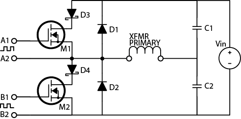
The circuit diagram is depicted below. A standard function generator is configured to produce a square wave. The frequency of this square wave must be adjusted to match the resonant frequency of the coil (approximately 600 kHz). Next, the gate drive board amplifies this signal to the appropriate level for driving power MOSFETS. A gate drive transformer isolates this low voltage gate drive board from the H bridge, which runs at 160 volts. The H bridge converts direct current to high frequency alternating current, which drives the air core coil at its resonant frequency.

Table of Contents

  1. Test Equipment – necessary for building and testing this device
  2. Gate Drive Board – a basic circuit for controlling high-power switches
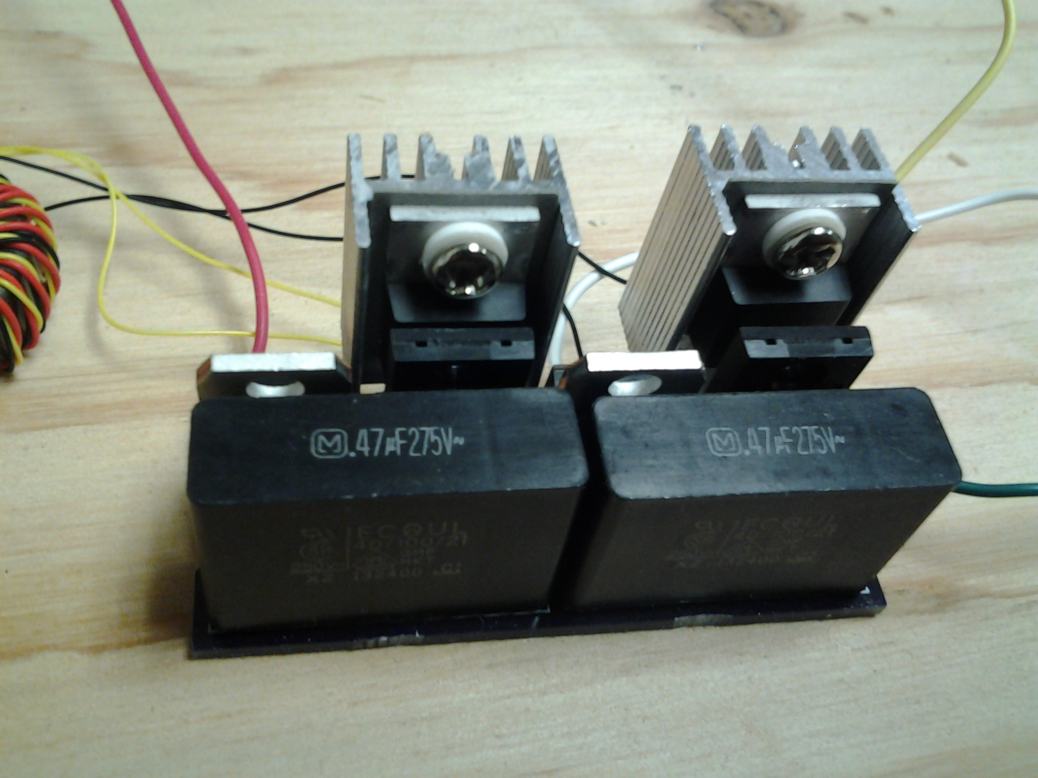
  3. Half H Bridge Board – converts 160VDC to 600kHz alternating current
  4. Primary and Secondary Coil – the main air core transformer (Tesla coil)
  5. Gate Drive Transformer – isolates the gate drive from the H bridge
  6. Completing the System – how to wire together items 1 to 5
  7. Where to Find Parts
  8. Links

1. Test Equipment

Digital Multimeter – A digital multimeter is required for checking supply voltages and identifying damaged components. With care, it can also be used to measure power consumption and analyze circuit performance.

LRC Meter – A precision LRC meter can measure the leakage inductance and magnetizing inductance of the gate drive transformer. It can also be used to characterize the air core transformer. The Vichy DM4070 (available on eBay) has the 1uH accuracy needed for this application. It is possible, but inconvenient, to measure inductance without an LRC meter.

Soldering Iron – A soldering iron is used to assemble the PC boards, and to make a few other connections.

Oscilloscope – If the circuits described here are constructed exactly as described, they should work correctly. In practice, however, minor construction variations can change the behavior of the circuits significantly. An oscilloscope can be used to check for correct operation, and is essential for any experimenter who wishes to design RF circuits from scratch.

Function Generator – An HP 3311A function generator is used to provide the signal for this SSTC. Any function generator can be used as long as it can produce a square wave with a range of 0V to 10V. The frequency must be adjustable from 100kHz to 1MHz. If you can not find one, you can build a simple square wave generator instead.

DC Lab Grade Power Supply – Good lab grade power supplies are available on eBay. A 12VDC regulated plug-in power supply can also be used.

2. Gate Drive Board

The signal from a function generator is not strong enough to drive power transistors. The high performance gate drive circuit described below will amplify the signal to levels that enable high speed switching.

Parts Needed

  • TC4421, TC4422
  • 5 Ohm, 2W resistor
  • 10uF Capacitor
  • 100nF Capacitor
  • Wire

PC Board Fabrication

The PC board can be manufactured by a company such as Osh Park. Upload the following files to their website, and they will process your order.

double_ended_gate_driver_v1

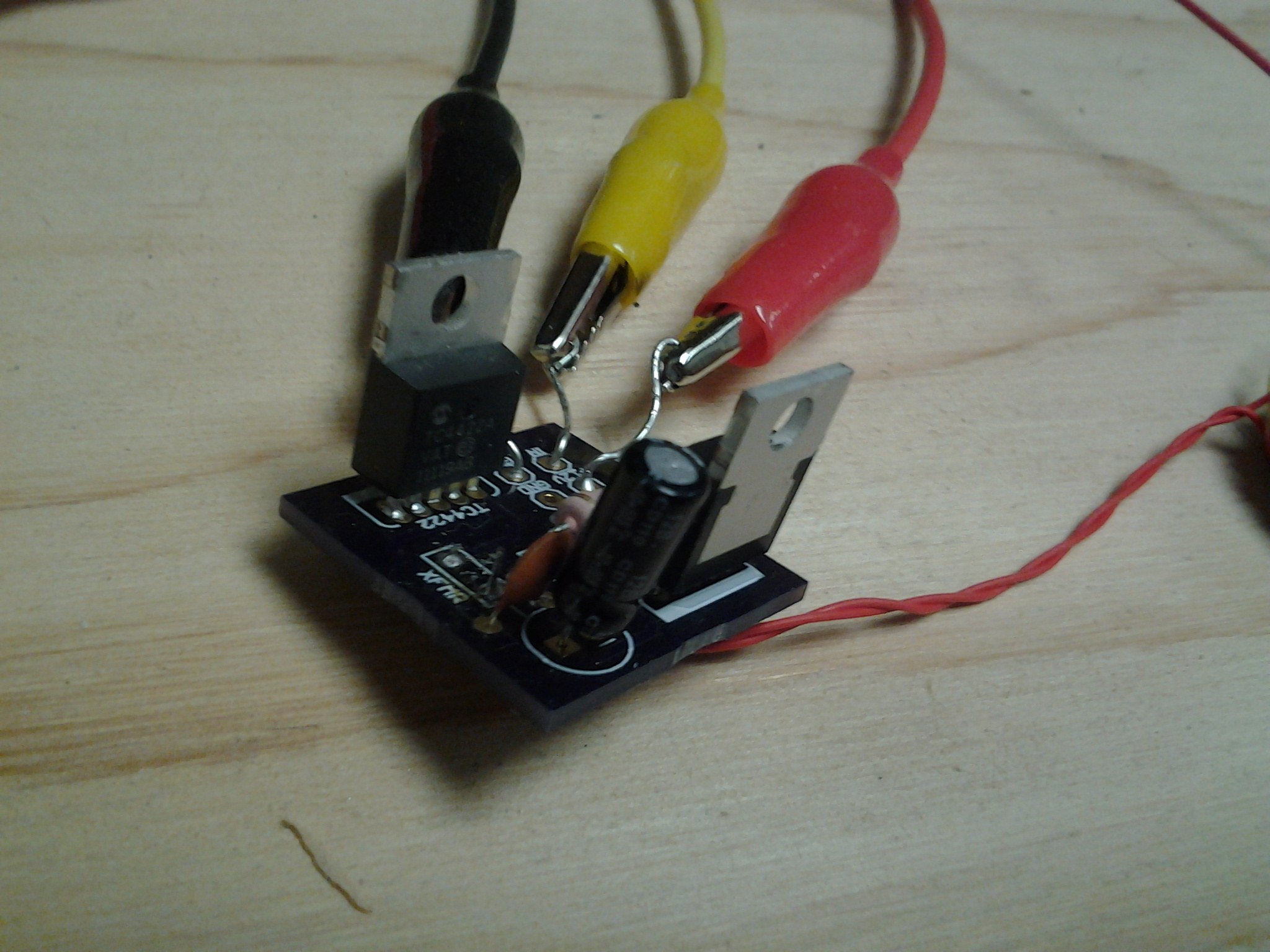
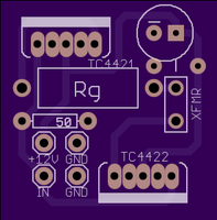
The finished board should look like this, and should measure approximately 1″ x 1″:

Front:  Back: 

PC Board Assembly

  1. The TC4421 and TC4422 ICs are designed for use as a MOSFET gate drive. Together, they form a small H bridge inverter that converts 12VDC to high frequency AC.
  2. The 50 Ohm input resistor should only be used in conjunction with a function generator that is calibrated for a 50 Ohm load. This resistor must be omitted if you are using a regular function generator, a 555 timer, or a 4046 VCO.
  3. The 100nF and 10uF capacitors provide power supply stability, and they should not be omitted. The MOSFETS draw very large currents while turning on and off, and the capacitors can provide this current instantaneously.
  4. The purpose of Rg is to improve the quality of the gate drive waveform. If it is omitted, the parasitic inductance of the circuit can cause ringing in the waveforms. A 5 Ohm resistor can be used for Rg, but experimentation will be needed if an optimal value is desired.
  5. X1 is the gate drive transformer. It will be described later.
  6. Attach wires to all of the inputs on the circuit board. These wires will connect the board to a 12 V power supply, and to a function generator.

3. Half H Bridge Board

The Half H Bridge is a high power inverter circuit. It converts DC to high frequency AC, which is used to drive the Tesla coil.

Parts Needed

  • Half H Bridge Board
  • 2 FPDF16N60 MOSFETs
  • 2 High Speed Diodes
  • 2 Schottky Diodes
  • 2 Polypropylene Film Capacitors

PC Board Fabrication

The PC board can be manufactured by a company such as Osh Park. Upload the following files to their website, and they will process your order.

half_h_v1

The finished board should look like this, and should measure approximately 1″ x 2″:

Front:  Back: 

PC Board Assembly

  1. M1 and M2 are high power MOSFETS. FDPF33N25 from Fairchild Semiconductor
  2. D1 and D2 are ultrafast rectifier diodes. BYC10DX-600 by NXP Semiconductor
  3. D3 and D4 are schottky rectifiers. STPS745 from ST Microelectronics
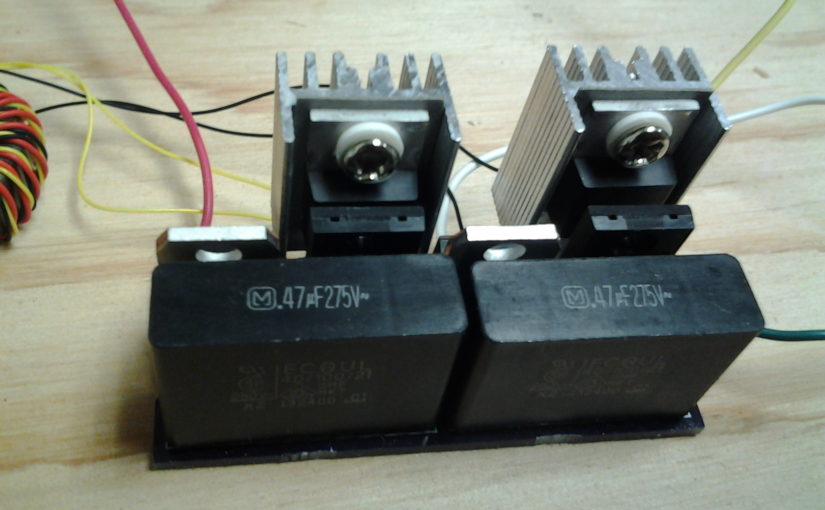
  4. C1 and C2 are film capacitors. 470nF, 275V. ECQ-U2A474ML from Panasonic
  5. The small components drawn on the board are optional Transient Voltage Suppressors – pairs of back-to-back zener diodes that protect the MOSFET gates from any voltage exceeding a certain threshold. If measures are taken to prevent the waveform from ringing above the gate’s maximum safe voltage, these components can be omitted.

4. Primary and Secondary Coils

The Tesla coil itelf consists of two coils: one with just a few turns, and one with several hundred turns. For this project, I re-used the transformer from a low-power solid state Tesla coil kit sold by Eastern Voltage Research. The parts are, however, readily available.

Parts Needed

  • Coil Form – 4.2″ OD ABS or PVC Pipe, Thin Wall
  • 30AWG Copper Magnet Wire
  • Wire for Primary Coil

Assembly Instructions

  1. The secondary coil can be wound on any cylindrical form of proper diameter. I used a small lathe to wind mine. A 630 turn coil can also be wound by hand.
  2. A thin layer of polyurethane can be applied to secure the windings to the coil.
  3. The primary coil should be separated from the secondary. A slightly larger plastic pipe should be used as the coil form. Only 3 turns are needed.
  4. The top of the secondary should be soldered to a short, thick wire. If the thin copper wire emits a spark, it will melt quickly.
  5. The bottom of the secondary coil should be connected to earth ground. It can be wired to the ground prong of a power outlet, or to a cold water pipe.
  6. The primary coil connects to the half H bridge as shown in the first diagram.

5. Gate Drive Transformer

The gate drive transformer isolates the gate drive board from the H bridge board.

Parts Needed

  • Amidon FT-50A-J Core
  • Wire Wrap Wire

Assembly Instructions

  1. Wire wrap wire is recommended for this transformer. It consists of a thin silver-plated wire with very tough insulation. If copper magnet wire is used instead, make sure to wrap the core in electrical tape so that it does not scratch away the insulation.
  2. Twist 3 2-foot long strands of wire wrap wire together.
  3. Wrap 10 turns of twisted wire on the ferrite core, and strip away the insulation at the ends.

6. Completing the System

Connect together the components as shown in the schematic diagram found at the beginning of this post. Although the SSTC can be connected directly to the power line, it is better to use an isolation transformer for testing purposes. Otherwise, it may not be possible to use an oscilloscope to test the circuit. I used an antique VIZ Isotap II transformer, which includes a built-in fuse. The AC current from this transformer must be rectified before it is fed to the half H bridge. A 10 amp (approximate) rectifier diode or full wave rectifier bridge can be used for this purpose.

The following steps should be followed when powering up the system:

  1. Configure the function generator to produce a 600kHz square wave, swinging from 0V to 10V. Use an oscilloscope to verify that the gate drive board is receiving a proper square wave.
  2. Apply 12VDC to the gate drive board, and make sure that the output is swinging with 12V amplitude (24V peak to peak across the primary coil of the gate drive transformer).
  3. If possible, use an adjustable isolation transformer to power the half H bridge board, starting with a low voltage and working your way up to 160VDC. WARNING: If you are not using an isolation transformer, you can not connect your oscilloscope probe to the secondary side of the gate drive transformer. The oscilloscope probe is grounded.
  4. Adjust the frequency of the function generator by sweeping from around 400kHz to 700kHz. When you hit the resonant frequency, there should be sparks.

7. Where to Find Parts

8. Links

Steve Ward’s Website – Steve Ward does a lot of work with DRSSTCs, which produce longer sparks than the traditional SSTC described here. As far as I know, his site is home to the largest, most powerful SSTCs.

Richie Burnett’s Website – Richie built a similar SSTC to the one described here, but he did so about 15 years ago. His site is still the best source for information on SSTC operating principles and theory. It also contains information on spark gap Tesla coils, Class E SSTCs, and induction heating.

Jan Wagner’s Website – Jan has published many useful circuits and design notes.

Texas Instruments Application Notes

  • SLUP169 – Design and Application Guide for High Speed MOSFET Gate Drive Circuits – Laszlo Balogh
  • SLUP123, SLUP124, SLUP125, SLUP126, SLUP127 – Magnetics Design for Switching Power Supplies – Lloyd Dixon

Eastern Voltage Research – Dan McCauley has written a book on DRSSTCs, and also sells SSTC kits. I purchased some of his products, and found them very interesting.

NOTE: This post was originally published January 2015 (old website).

CNC Drilling Machine

Back in 2007, I used to fabricate my own printed circuit boards using the toner transfer / ferric chloride etching process. This produced excellent copper trace quality, but drilling holes for all the component leads was a challenge. I decided to build a CNC machine to automate this task.

A program running on a computer reads instructions from a drill file generated by CAD software, and uses the serial port to send motion coordinates to an ATMega16 microcontroller. This microcontroller handles all of the stepper motor timing and input/output functions. A separate driver board boosts the microcontroller’s logic-level signals to activate the motor and relay coils. Each of the three stepper motors controls a linear slide that offers one degree of freedom between the workpiece and rotary tool. A relay controls the rotary tool itself.

Linear Slides and Frame


This is a 3-axis CNC machine. Each axis consists of a stepper motor, a lead screw, and a platform mounted on a linear slide. I purchased the mechanical components as a customized kit from Modular CNC (shown above).

The wooden frame was constructed from a sheet of readily-available MDF (fiberboard). With careful planning, I was able to cut all of the frame components from a 3/4″ x 24″ x 48″ panel. Once the frame was complete, I attached the three linear slides to it with wood screws.

Drive Board

The drive board uses power transistors to switch the stepper motor windings on and off. I used unipolar stepper motors, which are easily controlled by a single transistor for each winding.

Control Board

The control board consists of an AVR microcontroller and associated hardware. It receives instructions from a PC, and generates control signals for the drive board. The control board that I used for this project is the AVR-P40-8515, purchased from eBay.

Power Supply

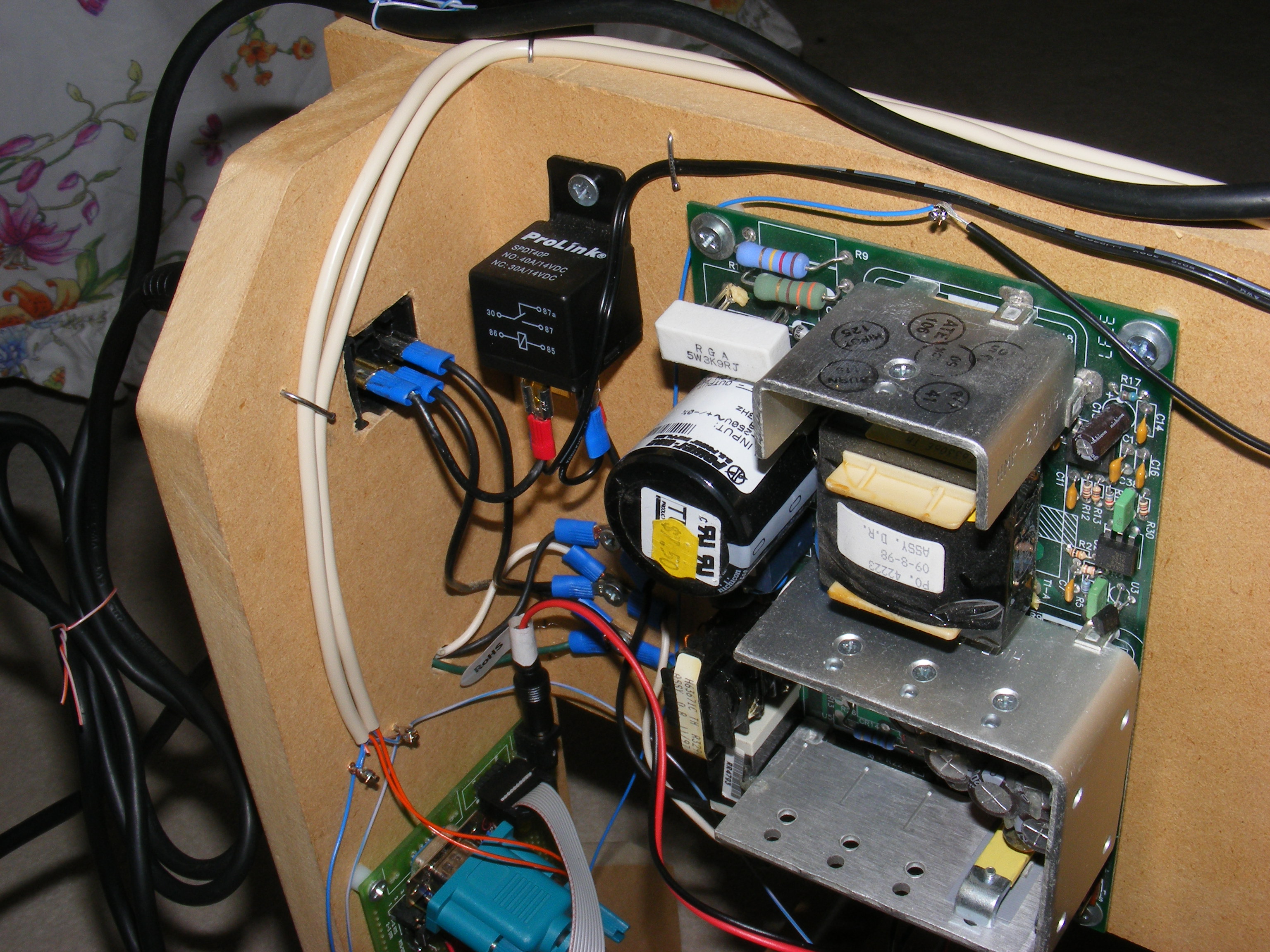
The power supply shown above provides 5 VDC for the control electronics, and 12 – 24 VDC for the stepper motors. Also shown is a relay, used to control the rotary tool. The rotary tool was mounted to the Z-axis platform using a fence post bracket, and connected to the relay using a power outlet.

Firmware / Software / Schematic