Back in 2007, I used to fabricate my own printed circuit boards using the toner transfer / ferric chloride etching process. This produced excellent copper trace quality, but drilling holes for all the component leads was a challenge. I decided to build a CNC machine to automate this task.
A program running on a computer reads instructions from a drill file generated by CAD software, and uses the serial port to send motion coordinates to an ATMega16 microcontroller. This microcontroller handles all of the stepper motor timing and input/output functions. A separate driver board boosts the microcontroller’s logic-level signals to activate the motor and relay coils. Each of the three stepper motors controls a linear slide that offers one degree of freedom between the workpiece and rotary tool. A relay controls the rotary tool itself.
Linear Slides and Frame


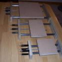
This is a 3-axis CNC machine. Each axis consists of a stepper motor, a lead screw, and a platform mounted on a linear slide. I purchased the mechanical components as a customized kit from Modular CNC (shown above).
The wooden frame was constructed from a sheet of readily-available MDF (fiberboard). With careful planning, I was able to cut all of the frame components from a 3/4″ x 24″ x 48″ panel. Once the frame was complete, I attached the three linear slides to it with wood screws.
Drive Board

The drive board uses power transistors to switch the stepper motor windings on and off. I used unipolar stepper motors, which are easily controlled by a single transistor for each winding.
Control Board

The control board consists of an AVR microcontroller and associated hardware. It receives instructions from a PC, and generates control signals for the drive board. The control board that I used for this project is the AVR-P40-8515, purchased from eBay.
Power Supply

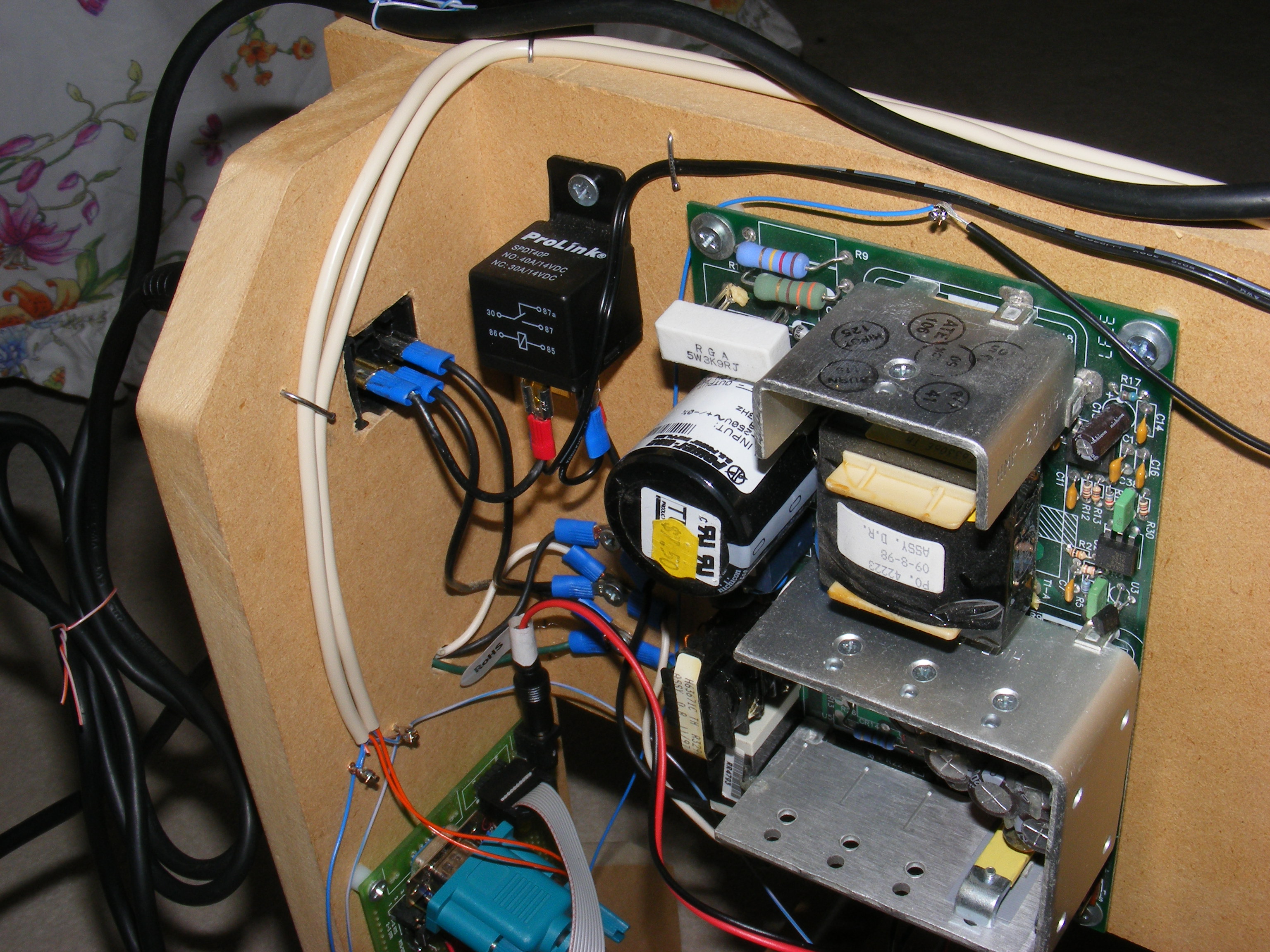
The power supply shown above provides 5 VDC for the control electronics, and 12 – 24 VDC for the stepper motors. Also shown is a relay, used to control the rotary tool. The rotary tool was mounted to the Z-axis platform using a fence post bracket, and connected to the relay using a power outlet.
Firmware / Software / Schematic
- Schematic – the original schematic used for this project (I ended up using an ATMega16 instead)
- cnc_firmware_2007_version_asm – old assembly language firmware for the ATMega8
- cnc_firmware_2009_version_c – newer c language firmware (not sure if this was the final version that was installed on the ATMega16)
- cnc_software – allows the computer to send data to the serial port
- My project is partially based on Jonathan Westhues’ similar machine.
