The system described in this post is a continuous wave solid state Tesla coil (CW SSTC). As seen in the video above, it produces sparks that look very different from those of a traditional Tesla coil. The continuous wave output gives rise to thicker, brighter, shorter sparks that appear almost sword-like.
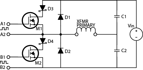
The circuit diagram is depicted below. A standard function generator is configured to produce a square wave. The frequency of this square wave must be adjusted to match the resonant frequency of the coil (approximately 600 kHz). Next, the gate drive board amplifies this signal to the appropriate level for driving power MOSFETS. A gate drive transformer isolates this low voltage gate drive board from the H bridge, which runs at 160 volts. The H bridge converts direct current to high frequency alternating current, which drives the air core coil at its resonant frequency.
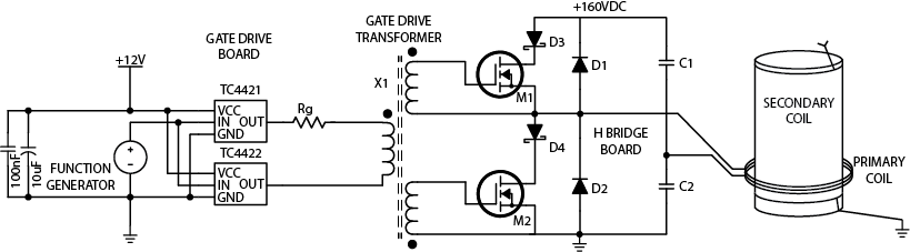
Table of Contents
- Test Equipment – necessary for building and testing this device
- Gate Drive Board – a basic circuit for controlling high-power switches
- Half H Bridge Board – converts 160VDC to 600kHz alternating current
- Primary and Secondary Coil – the main air core transformer (Tesla coil)
- Gate Drive Transformer – isolates the gate drive from the H bridge
- Completing the System – how to wire together items 1 to 5
- Where to Find Parts
- Links
1. Test Equipment
Digital Multimeter – A digital multimeter is required for checking supply voltages and identifying damaged components. With care, it can also be used to measure power consumption and analyze circuit performance.
LRC Meter – A precision LRC meter can measure the leakage inductance and magnetizing inductance of the gate drive transformer. It can also be used to characterize the air core transformer. The Vichy DM4070 (available on eBay) has the 1uH accuracy needed for this application. It is possible, but inconvenient, to measure inductance without an LRC meter.
Soldering Iron – A soldering iron is used to assemble the PC boards, and to make a few other connections.
Oscilloscope – If the circuits described here are constructed exactly as described, they should work correctly. In practice, however, minor construction variations can change the behavior of the circuits significantly. An oscilloscope can be used to check for correct operation, and is essential for any experimenter who wishes to design RF circuits from scratch.
Function Generator – An HP 3311A function generator is used to provide the signal for this SSTC. Any function generator can be used as long as it can produce a square wave with a range of 0V to 10V. The frequency must be adjustable from 100kHz to 1MHz. If you can not find one, you can build a simple square wave generator instead.
DC Lab Grade Power Supply – Good lab grade power supplies are available on eBay. A 12VDC regulated plug-in power supply can also be used.
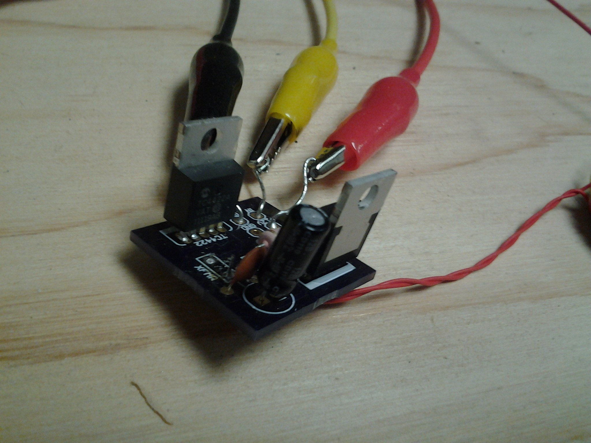
2. Gate Drive Board
The signal from a function generator is not strong enough to drive power transistors. The high performance gate drive circuit described below will amplify the signal to levels that enable high speed switching.
Parts Needed
- TC4421, TC4422
- 5 Ohm, 2W resistor
- 10uF Capacitor
- 100nF Capacitor
- Wire
PC Board Fabrication
The PC board can be manufactured by a company such as Osh Park. Upload the following files to their website, and they will process your order.
The finished board should look like this, and should measure approximately 1″ x 1″:
Front: 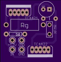 Back:
Back: 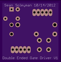
PC Board Assembly

- The TC4421 and TC4422 ICs are designed for use as a MOSFET gate drive. Together, they form a small H bridge inverter that converts 12VDC to high frequency AC.
- The 50 Ohm input resistor should only be used in conjunction with a function generator that is calibrated for a 50 Ohm load. This resistor must be omitted if you are using a regular function generator, a 555 timer, or a 4046 VCO.
- The 100nF and 10uF capacitors provide power supply stability, and they should not be omitted. The MOSFETS draw very large currents while turning on and off, and the capacitors can provide this current instantaneously.
- The purpose of Rg is to improve the quality of the gate drive waveform. If it is omitted, the parasitic inductance of the circuit can cause ringing in the waveforms. A 5 Ohm resistor can be used for Rg, but experimentation will be needed if an optimal value is desired.
- X1 is the gate drive transformer. It will be described later.
- Attach wires to all of the inputs on the circuit board. These wires will connect the board to a 12 V power supply, and to a function generator.
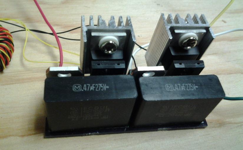
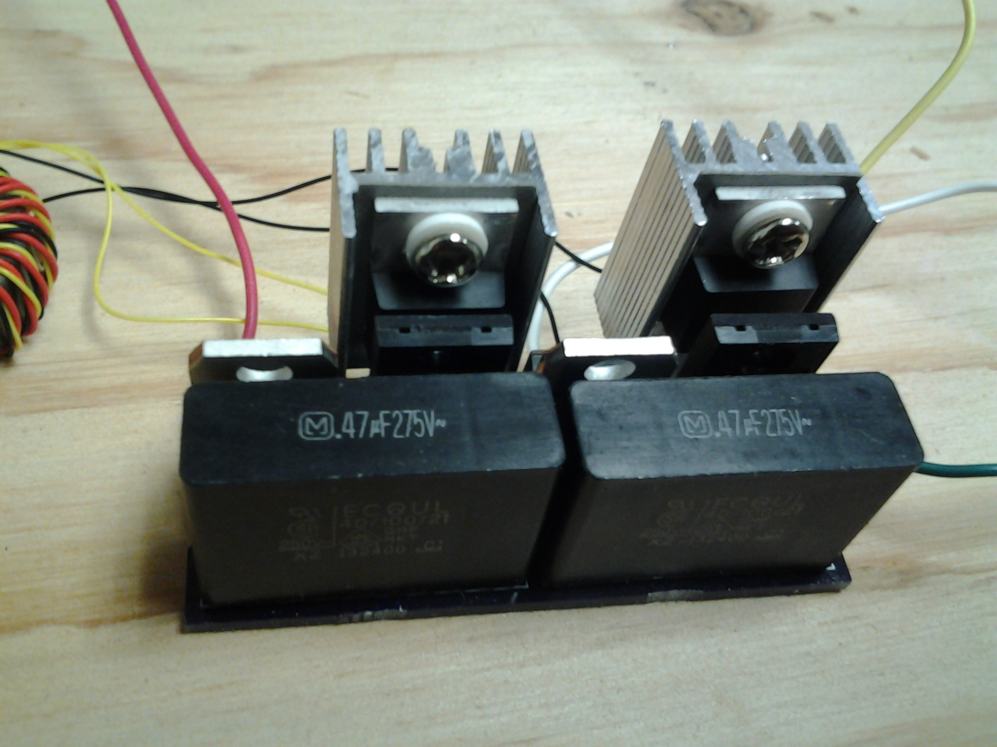
3. Half H Bridge Board
The Half H Bridge is a high power inverter circuit. It converts DC to high frequency AC, which is used to drive the Tesla coil.
Parts Needed
- Half H Bridge Board
- 2 FPDF16N60 MOSFETs
- 2 High Speed Diodes
- 2 Schottky Diodes
- 2 Polypropylene Film Capacitors
PC Board Fabrication
The PC board can be manufactured by a company such as Osh Park. Upload the following files to their website, and they will process your order.
The finished board should look like this, and should measure approximately 1″ x 2″:
Front: 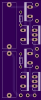 Back:
Back: 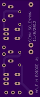
PC Board Assembly
- M1 and M2 are high power MOSFETS. FDPF33N25 from Fairchild Semiconductor
- D1 and D2 are ultrafast rectifier diodes. BYC10DX-600 by NXP Semiconductor
- D3 and D4 are schottky rectifiers. STPS745 from ST Microelectronics
- C1 and C2 are film capacitors. 470nF, 275V. ECQ-U2A474ML from Panasonic
- The small components drawn on the board are optional Transient Voltage Suppressors – pairs of back-to-back zener diodes that protect the MOSFET gates from any voltage exceeding a certain threshold. If measures are taken to prevent the waveform from ringing above the gate’s maximum safe voltage, these components can be omitted.
4. Primary and Secondary Coils
The Tesla coil itelf consists of two coils: one with just a few turns, and one with several hundred turns. For this project, I re-used the transformer from a low-power solid state Tesla coil kit sold by Eastern Voltage Research. The parts are, however, readily available.

Parts Needed
- Coil Form – 4.2″ OD ABS or PVC Pipe, Thin Wall
- 30AWG Copper Magnet Wire
- Wire for Primary Coil
Assembly Instructions
- The secondary coil can be wound on any cylindrical form of proper diameter. I used a small lathe to wind mine. A 630 turn coil can also be wound by hand.
- A thin layer of polyurethane can be applied to secure the windings to the coil.
- The primary coil should be separated from the secondary. A slightly larger plastic pipe should be used as the coil form. Only 3 turns are needed.
- The top of the secondary should be soldered to a short, thick wire. If the thin copper wire emits a spark, it will melt quickly.
- The bottom of the secondary coil should be connected to earth ground. It can be wired to the ground prong of a power outlet, or to a cold water pipe.
- The primary coil connects to the half H bridge as shown in the first diagram.
5. Gate Drive Transformer
The gate drive transformer isolates the gate drive board from the H bridge board.
Parts Needed
- Amidon FT-50A-J Core
- Wire Wrap Wire
Assembly Instructions
- Wire wrap wire is recommended for this transformer. It consists of a thin silver-plated wire with very tough insulation. If copper magnet wire is used instead, make sure to wrap the core in electrical tape so that it does not scratch away the insulation.
- Twist 3 2-foot long strands of wire wrap wire together.
- Wrap 10 turns of twisted wire on the ferrite core, and strip away the insulation at the ends.
6. Completing the System
Connect together the components as shown in the schematic diagram found at the beginning of this post. Although the SSTC can be connected directly to the power line, it is better to use an isolation transformer for testing purposes. Otherwise, it may not be possible to use an oscilloscope to test the circuit. I used an antique VIZ Isotap II transformer, which includes a built-in fuse. The AC current from this transformer must be rectified before it is fed to the half H bridge. A 10 amp (approximate) rectifier diode or full wave rectifier bridge can be used for this purpose.
The following steps should be followed when powering up the system:
- Configure the function generator to produce a 600kHz square wave, swinging from 0V to 10V. Use an oscilloscope to verify that the gate drive board is receiving a proper square wave.
- Apply 12VDC to the gate drive board, and make sure that the output is swinging with 12V amplitude (24V peak to peak across the primary coil of the gate drive transformer).
- If possible, use an adjustable isolation transformer to power the half H bridge board, starting with a low voltage and working your way up to 160VDC. WARNING: If you are not using an isolation transformer, you can not connect your oscilloscope probe to the secondary side of the gate drive transformer. The oscilloscope probe is grounded.
- Adjust the frequency of the function generator by sweeping from around 400kHz to 700kHz. When you hit the resonant frequency, there should be sparks.

7. Where to Find Parts
- Digikey – electronic components
- TemCo Industrial Power – copper magnet wire
- Amidon – ferrite core for gate drive transformer
- Osh Park – custom pc boards
- BG Micro, All Electronics, Alltronics – surplus electronics and tools
- eBay – test equipment, tools
8. Links
Steve Ward’s Website – Steve Ward does a lot of work with DRSSTCs, which produce longer sparks than the traditional SSTC described here. As far as I know, his site is home to the largest, most powerful SSTCs.
Richie Burnett’s Website – Richie built a similar SSTC to the one described here, but he did so about 15 years ago. His site is still the best source for information on SSTC operating principles and theory. It also contains information on spark gap Tesla coils, Class E SSTCs, and induction heating.
Jan Wagner’s Website – Jan has published many useful circuits and design notes.
Texas Instruments Application Notes
- SLUP169 – Design and Application Guide for High Speed MOSFET Gate Drive Circuits – Laszlo Balogh
- SLUP123, SLUP124, SLUP125, SLUP126, SLUP127 – Magnetics Design for Switching Power Supplies – Lloyd Dixon
Eastern Voltage Research – Dan McCauley has written a book on DRSSTCs, and also sells SSTC kits. I purchased some of his products, and found them very interesting.
NOTE: This post was originally published January 2015 (old website).
Thanks so much for your website! I am a first-time coiler, and I have been doing a lot of reading (TCML) and many of the sites you reference. I’ve been a little confused about certain aspects of the hobby, like where to start, as the references I have found so far have (from the perspective of my limited knowledge) insufficient info for a newbie. Your site lays it out excellently. I’m a flame effects person and would like to add a dozen or so small TCs to a MIDI project I am working on to make a large (rather goofy) calliope. (a 10 second video of the flame prototype can be found here: https://www.youtube.com/watch?v=-8sDM2_J9J8
With your plans, I’m eager to start building and experimenting with coiling and modifying parameters. I’m curious… you don’t use the traditional top load; clearly it is working without it; was this just to simplify your design, or by not including it, you get a more optimal resonance frequency you desired?
Thanks again! I’m buying parts today!
Dirk
702 379 3948
Neat flame effects! About the topload: I have used this basic design both with and without. A topload (usually a toroid) reduces the resonant frequency, resulting in some performance trade-offs. On the positive side, a lower resonant frequency means that the switches turn on and off less often, which directly reduces losses. However, lower resonant frequency also increases the magnetizing current, which has the opposite effect on switching losses! One thing is for sure: If you do include a topload, it should have a breakout point – a sharp wire that encourages sparks to form at the appropriate location. This wire should point up or to the side to discourage sparks from connecting with the primary coil.
Hi Dirk
I wrote a long guide on how to design and build Tesla coils, mostly focused on the popular DRSSTC topology: http://kaizerpowerelectronics.dk/tesla-coils/drsstc-design-guide/
I also made a live stream video a while ago where I made a long talk about what resources to study, read and what websites to use to calculate all you need etc. https://www.youtube.com/watch?v=TP4J3eyZjyQ
Kind regards
Mads
thanks for sharing. I would like to expand your design and include an oscillator to the layout. Would you mind sharing your Eagle or KiCad schematics for editing?
https://www.eevblog.com/forum/projects/30-mhz-ad9850-dds-signal-generator-in-12$/
Unfortunately I no longer have the original files – they were lost because of a failed hard drive. I would suggest building your new oscillator circuit on a separate PCB, and test it with the provided H-bridge and gate drive board designs. Then (once everything is working) create a new PCB with oscillator, gate drive, and H-bridge.
Thank you very much!
I read this some months later than posted; however
I have a question about using both the TC4421 and 4422 to drive the MOSFETS; when we apply the signal (square wave), should not the output be a constant voltage? (when the inverting turns off the non inverting turns on and so forth) Maybe I am missing something…Many thanks again
It’s best to think of the TC4421 and TC4422 outputs as being high or low as opposed to on or off. When the output is high (positive), current can flow out of the pin. When the output is low (zero), current can flow into the pin. The TC4421 and TC4422 each form one of the two sides of a full H-bridge circuit.
When the input signal is high, the TC4421 (inverting) driver outputs low and the TC4422 (non-inverting) driver outputs high. Therefore, current flows from the output pin of the TC4422 to the output pin of the TC4421. When the input signal is low, the TC4421 (inverting) driver outputs high and the TC4422 (non-inverting) driver outputs low. Then, the current flows in the opposite direction, from the output pin of the TC4421 to the output pin of the TC4422. Therefore, switching the input signal between low and high causes the direction of current flow through the gate drive transformer to switch back and forth.